Technical Specifications
X-Air F Gumnam
Construction
01 / 08
X-Air "F" Model - Flaps
The "F" model or "FLAP" model is an evolution of the standard X-Air, it has three stage flaps to slow the aircraft down for landing. The wing and tail on the Flap model also differs from the standard X-Air. The flap model flies faster than the standard X-Air because of the different profile wing and the flap model also costs slightly more but comes standard with rear wheel pants, doors and wide entry.
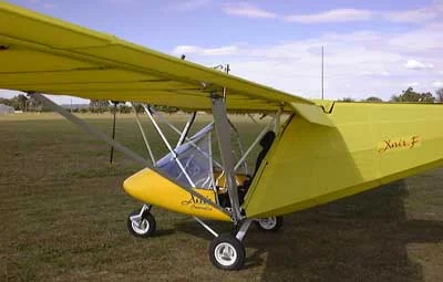
The X-Air FLAP Model
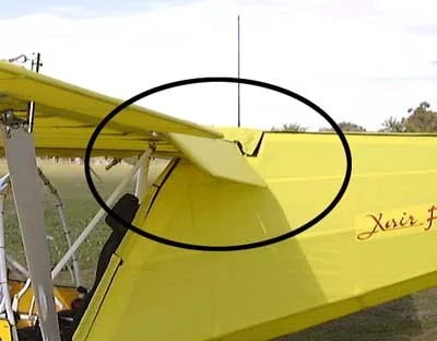
Close-up picture of the Flaps
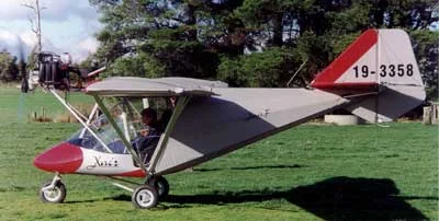
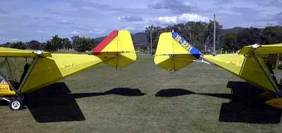
Notice how the FLAP model's tail differs from the standard model on the right
Core Construction & Materials
- Frame & Structure: Built from bolted aluminum alloy tubing, mated to a central welded Cromoly/steel cockpit safety cage.
- Sailcloth Covering: Wings, ailerons, flaps, and tail surfaces are wrapped in pre-sewn 185 g/m² Dacron polyester fabric envelopes.
- Keel & Struts: Structured around a central heavy-duty keel tube with V-struts and jury struts supporting the high-mounted wings.
- Enclosure: Features a fiberglass/composite central pod and optional or standard transparent "Lexan" doors and windshields.
- Landing Gear: Tricycle configuration equipped with oleo shock absorbers on all three wheels, a steerable nosewheel, and mainwheel brakes.
Assembly & Build Process
- Kit Type: Supplied as a quick-build kit (typically taking roughly 100 to 200 hours to assemble).
- No Specialized Tools Required: Assembled primarily with standard hand tools (such as small spanners and quarter-inch drive sockets).
- Assembly Sequence:
- Assemble the main axle and central keel assembly, keeping bolts loose initially to prevent structural binding or alignment errors.
- Level the frame using jacks and a spirit level, then align and lock the vertical kingpost and tail boom.
- Bolt the central cockpit cage, seats, and dual-axis/engine controls into place.
- Slide or wrap the pre-sewn Dacron sailcloth envelopes over the aluminum wing and tail structures.
- Install the tractor engine (such as a Rotax 582, Rotax 912, or Jabiru 2.2), reduction drive, propeller, and instrumentation panel.
- Rig the 3-position in-flight adjustable flaps, cables, and aileron control surfaces.